Catalog
Products
Order
Links
Contact


REVIEWS

On-Board Battery Checker
Price: $16.00
reviewed in Jet International, February/March 2001, p.53. Reprinted with permission.

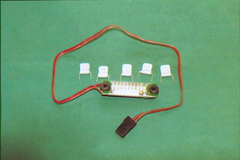
A range of on-board battery voltage monitors has been introduced. The monitors are supplied with a selection of plug-in resistors marked 4.8v, 6.0v, 7.2v, 8.4v, and 9.6v to enable the monitor to be used with NiCad batteries with 4 to 8 cells. In operation the unit is installed in a visible place on the model with double-sided adhesive tape or two screws through the rubber grommets. The display has three red, four yellow and three green LEDs.

If any green LED is lit the battery voltage is regarded as safe. If a yellow LED is lit the battery is low enough to serve as a warning that not much battery capacity remains. If a red LED is lit the battery voltage is dangerously low.

Automix
reviewed by Dave Bowen, published in Radio Control Jet International, April/May 1999, pp.10-11. Reprinted with permission.

I was asked by the Editor if I would like to experiment with a device that would look after the fuel mixture settings of the fan engine so I could concentrate on my flying. Was he trying to tell me something? 
A parcel arrived in a few days and on opening the package my first thought was "how do I get all that stuff in the model?" There were a lot of bits to this device which were all safely packed for transit but a closer look showed that not all the components are installed in the model.

Starting at the top we have:

The Automix unit.
An LCD indicator panel.
Exhaust Gas Temp Sensor with rubber washer and grommet.
Loctite 71 thread lock
Instructions.
Fuel proof Automix decal.

I know the old phrase 'if in doubt read the instructions' but in this case do it. They are very good, clearly written and explain in great detail exactly what to do.

So how does the Automix work?
Basically, it monitors the exhaust gas temperature and automatically adjusts the mixture needle via the inflight adjustment to keep the engine running at its most efficient temperature. Putting it simply so even I can understand, once the optimum temperature has been set on the Automix, should the engine lean out then the temperature of the exhaust will rise. The Automix senses this via the temperature sensor that is installed into the header and opens the mixture valve to richen the needle valve setting, thus lowering the exhaust temperature.

Initial Installation
The Automix is connected between the receiver and the mixture control valve servo. So the first job is to connect the sensor lead to the Automix (this is connected to the header later). Now connect the LCD display unit to the Automix. The linkage from the servo to the mixture valve is important and must be set 11 mm from the center of the servo arm. The other end must be connected to the outer hole on the mixture valve arm, which is clearly shown diagrammatically in the instructions. Next on the agenda is to set up and do some testing. To do this you need to set up your radio gear. The mixture knob must be set at 50% i.e. in the middle. High and low ATV must be set to maximum. The L.E.D. on the Automix will be on and the surrounding temperature will show on the LCD display panel. Check that when you operate the mixture contol open is open and closed is closed. Next you need to set the system by pressing the button on the Automix for 1 second. Now hold the temperature sensor between thumb and forefinger (that's why we have not installed this component yet) and you will see the mixture valve open and an increase in temperature will show on the display panel.

Temperature Sensor Installation
A hole has to be drilled and tapped in the header 3/4" inch from the engine beginning f the header. Once this task is completed, the sensor is carefully screwed in (Loctite is supplied just for this purpose) having passed the lead through the cover cap. The remainder of the lead is routed through to the Automix securing it along the way. This sequence is again shown clearly in the instructions. Right we are now ready, let's go flying!

Final setup and Flying
Wait for it. Before you send your jet off into the skies there are still a few things to do. You must set the Automix up first otherwise it won't work correctly. First start your engine. Now run the engine up to full throttle. Once there, adjust your mixture using your transmitter knob until optimum performance is reached. Push the red button on the Automix and the red LED which should be on, will now flash. This is what the instructions say and they have the final word. Now glance at the LCD display and you will see the exhaust gas temperature being displayed. Throttle back to idle and disconnect the LCD display. You are now ready for flying. The Automix has not yet taken over your mixture control as yet so you will still have control over the mixture during that vital takeoff period when the Automix will sense the temperature that it was set at. This is the threshold temperature. When the Automix senses the threshold temperature for the second time, it wil activate and take over the mixture control for you. Even though the Automix is looking after your engine you still have control. By turning the mixture control on your transmitter you are able to raise or lower the set temperature. The Automix needs to be set up before every flight which is no problem. Next time move selector switch to set, adjust the peak temp., press the set button and move the selector to run. That's it. You're ready to fly! An extra addition is that the LCD display becomes a battery checker at the flick of a switch--brilliant!

Did it or didn't it?
Well you might be wondering if the Automix actually worked and how do you check that it does. I ran the engine up and set it all up. I then adjusted the throttle to simulate the second threshold temperature. I tipped the aircraft onto its nose (my fuel tank is up front) to lean out the engine and the remote needle moved richening the mixture. Conclusive proof that it does work. Incidentally my wings come off the model so I can see the remote needle and its servo, just in case you were going to ask. I flew the aircraft for three or four flights during the test session and found no problems at all. Control response was smooth there's no doubt that this device will protect your engine therefore giving longer life. The safety aspect of fitting a unit such as the Automix is an important one, of course, and anything that improves safety can't be bad, can it? Full marks to Mini Hobby for producing this simple and easy to use unit.


AutoSpeed

Three Reviews:

(1) reviewed in Radio Control Jet International, April/May 2000, p.65. Reprinted with permission.


Mini Hobby Autospeed

Mini Hobby ATL, inl. has developed an automatic speed control device called Autospeed that enhances flight safety by controlling maximum and minimum aircraft speed.

Autospeed uses a microprocessor and a precise pressure sensor to control the speed of an aircraft to a set value by controlling the engine power. Pre-set values for maximum (VNE) and minimum (VS) can be selected. In flight, the automatic mode can be activated by an auxiliary channel to hold the current speed. The automatic mode is disengaged by the auxiliary channel or by smartly moving the throttle stick. You have a working pitot tube on your model as in the photograph, so form a queue behind me!

Low Speed Protection: If the Auto mode is selected when the speed is below the Minimum pre-set, the unit will hold the minimum set speed rather than the current speed. Example: if flying at 35 mph and the Minimum speed is set at 45 mph, the unit will keep the speed at 45 mph. This feature will help to prevent a stall condition. Overspeed protection: whenever the speed exceeds the maximum set, power is automatically reduced. 


(2) reviewed by Don Lowe, published in RCM, June 2000, pp.44,46. Reprinted with permission.

Technology

I love it! This R/C hobby has something for everyone; from the most simple trainer model with no frills and very reliable inexpensive radios to multi-engine turbine-powered models worth $20K!

Big models are very popular and the availability of ready-built beautiful airplanes and super engines assures lots of fun, for lots of bucks!

I recently witnessed a demo of a speed control device for models which allows one to dial in a safe (never exceed) velocity and a minimum (please don't stall) speed. It is the development of Mini Hobby ATL Inc., and Roy Dutton of the R/C World Flyers. Essentially, it senses airspeed and couples this information through the essential electronics to control the throttle. Now, all we need to know is what are these safe limits for each aircraft design.

You may know that currently AMA limits the thrust-to-weight of turbine models to control the max safe speed of these aircraft. It really would be best to have a device which does this automatically. How many models have you seen destroyed by control flutter? I have seen more than my share and have also survived several instances of it (except one).

Control flutter is an insidious killer, very little understood, and is speed dependent. If you ever encounter flutter, slow down quickly or you may lose the surfaces (and control). As an aside, flutter can be controlled by 91) keeping the velocity below flutter speed, (2) very stiff control set-ups, and (3) counter-balancing the control surfaces, a la full-scale practice.

A friend of mine recently lost a beautiful P-38 due to elevator flutter when he flew the aircraft at a little faster airspeed than normal. The full-scale P-38 had control surface counterbalances. Often, you can survive aileron or rudder flutter by rapidly slowing down, but elevator flutter is a killer, since the aircraft pitches down!

How many beautiful scale models have you seen damaged by stalling on the landing approach? Wouldn't it be neat to have a device that helps thwart that possibility? For further information on the availability of this gadget, contact: Mini Hobby ATL, Inc., 10266 NW 47th St., Sunrise, FL 33351, phone (954) 746-3095, fax (954) 746-3095, e-mail:

minihobby@compuserve.com

Incidentally, my very inventive friend, Roy Dutton, is working on a completely automated flight control system which will include automatic landing!

Stay tuned.


(3) reviewed in Model Airplane News, July 2000, p.33. Reprinted with permission.

Unique Things

Watching the airborne activities disclosed some interesting new things. How about Antonio Tahan's compact, lightweight, airborne device that limits speed to a preset point? Why, you ask? Well, a lot of these turbines can drive the airframes well beyond reasonable (and intelligent) speed limits; that is, the airframe will self-destruct before the engine does. A device such as this helps to ensure the safe operation of these models. Chris Huhn had one installed in his JetCat; it was set to a mere 180mph!


Voltage Regulator
reviewed by George Steiner, published in RCM, March 1999, p.121. Reprinted with permission.

In the past few years, an idea has caught on for the need to produce better voltage regulation for the on-board electrical operation of the servos and other equipment. Some investigations have shown that a wide variety of voltage bounce was being created under heavy loads with the use of a total raw voltage source like right off a 4-cell NiCd.

This prompted a solution to increase the input source voltage supply and electronically regulate a constant voltage to the receiver and servos under any kind of load. This appears to have solved the problem as it was designed to do. Now being offered is a Voltage Regulator by Mini Hobby ATL Inc., that goes between the ON/OFF switch and the receiver. The MH Regulator is a powerful unit, but keep in mind, if the device is not properly placed in operation per the manufacturer's specification, nothing is gained. For example, you can't use a low-capacity, higher voltage battery and expect the regulator to compensate for this error. In general, regulators for models require high capacity and higher source operating voltages with adequate wiring when being used to realize the potential they were designed for. This is true of the MH device that has a rating of over 7 amps peak load capability.

The Mini Hobby Regulator was run through a test and it followed close to the manufacturer's specification.... It showed no bad habits and it does consume some negligible power. (You do not get something for nothing.) The size, as one can observe..., is very small, with a weight of just .4 oz. with the connectors. It is easy to install between the receiver power input (marked as BAT in most cases) and the switch harness connection that was designated for the receiver power input.


ECU Turbine Controller
reviewed by Tom Wilkinson, published in Radio Control Jet International, December/January 1999, pp.28-29. Reprinted with permission.

MH Turbine Controllers have been designed and supplied for use with KJ-66, Turbomin and JPX kerosene burning engines and are therefore probably of great interest also to the "home builders" of gas turbines. The system is designed to control the electric motor which drives the fuel pump. Engine case pressure, referred to in the operating instructions as compressor discharge pressure (CDP), and exhaust gas temperature are monitored to provide automatic limiting of the fuel pump if the CDP rises above an adjustable pre-set limit, and shut down of the pump if the CDP falls below an adjustable pre-set limit or the temperature exceeds a pre-set (factory adjustable) value of 790°C.

The system supplied for review was the basic version V1.0 which does not have the over pressure shut-down facility. A unit supplied for use with the KJ-66 with over pressure limiting is designated version V1.1 and there is a version V2.0 which has the addition of a start button switch, which must be pressed to allow the pump to start. All versions can be upgraded to V2.0. The systems cost $275 for V1.0, $292 for V1.1 and $312 for V1.2.

A comprehensive set-up procedure is supplied with all versions of the controller which is easy to understand and implement. There are no fuel pump motor voltage adjustments to be made from the controllers as they rely upon being operated in conjunction with a "computer" radio system with the facility to adjust the throttle signal High and Low ATV. The Instruction Manuals gives comprehensive details of setting-up procedures.

The engine protection systems (under-pressure and over-temperature) both initiate a complete engine shut-down by stopping the fuel pump motor and preventing it from restarting until the radio receiver is switched off for three seconds. The over pressure limiting system prevents the throttle from causing the engine to run above the preset limit with the pilot retaining full control of the engine up to that limit.

During engine starting the pressure sensor will prevent the fuel pump from running until the engine case pressure exceeds a pre-set value. The pressure to be obtained before the fuel pump could run in the case of the review system was higher than that which can be obtained by the typical blower used to start some home-built engines, having been factory-set to 0.315 bar, however it can be adjusted to lower values for blower starting. The MH Turbine Controller instructions only address starting with compressed air, which should give turbine compressors speeds high enough to generate case pressures of 0.135 bar.

The thermocouple exhaust gas temperature (EGT) sensor causes an engine shut-down at a temperature of approximately 790°C. The over-temperature shut-down system will not cause an engine shut-down if the thermocouple is disconnected or the connecting wires are broken; the pump will keep running and would therefore continue to do so even if the exhaust gas temperature went beyond safe limits. At first sight this appears to be a short-coming but the manufacturer explained that this is a deliberate policy designed to give the maximum protection to the model aircraft. The argument is that if the EGT sensor malfunctions during engine starting the display will read zero and the operator will be aware of this and will initiate a shut-down manually, knowing that the over-temperature protection will fail. Once an engine has been started and is running at a satisfactory temperature it is unlikely to develop a fault, which would give rise to an over-temperature situation, which would not also be detected by the over- or under-pressure sensor. So, if the temperature probe fails on a healthy engine in the air it is undesirable to shut the engine down unless a real problem exists and that would be dealt with by the pressure sensor. An unnecessary engine shut-down immediately after take-off is definitely to be avoided!

The temperature monitoring circuit has adequate radio frequency suppression and does not suffer from spurious readings unless the radio control transmitter antenna is held (in the case of the reviewer's 35MHz Tx) closer than six inches from the thermocouple probe. If MH had not taken care of this it would be quite possible to initiate a shut down while ground running by just getting the Tx too close to the probe.

Versions V1.1 and V2.0 for the KJ-66 are factory set to limit the gas turbine's compressor discharge pressure (CDP) to 1.1 bar, (which is in line with current recommendations from Jesus Artes in respect of operating limits for the KJ-66 turbine wheel. However the over-pressure limit of the controller can be adjusted from 0.8 bar 1.5 bar.


JPX 260K Turbine Controller
reviewed by David Gladwin, published in Radio Control Jet International, April/May 1999, pp.14-16. Reprinted with permission.

In our recent review of the superb JPX 260K kerosene engine we described the fairly simple electronics which, in conjunction with a mechanical limiter on the fuel pump, control the engine's acceleration and maximum output. There can be great virtue in the simple and straightforward design philosophy of the Westbury electronics which work very well. However, AMA rules for the approval of this engine for use in the US 

require that the engine should have built-in protection to prevent damage and possible failure in the event of overspeed or overtemp. To meet the AMA requirements, Mini Hobby of Miami Florida, run by Antonio Tahan, a former DC10 pilot, has designed and is manufacturing a comprehensive turbine controller for the JPX 260K. Mini-Hobby is already producing a range of excellent electronic devices including the mixture controller for fan engines and the BVM Jet Guard which protects the 260P from loss of oil pressure and overtemp., within the fuselage as well as providing a range of acceleration curves.

The Mini Hobby JPX turbine controller consists of three main units, the controller itself which is linked to a thermocouple which is installed on the engine and a starter box with glow driver. The controller incorporates a sensor which monitors engine EGT and initiates an auto shutdown in the event of significant overtemp. The unit also provides the engine with acceleration control and will limit the maximum engine speed by monitoring the compressor output; there is, therefore, no requirement for an RPM sensor and none is fitted. This CDP (compressor discharge pressure) monitor will also initiate shutdown if engine CDP falls below a safe level which can be set by the operator. The JPX factory recommends a MINIMUM idle value of .2 bar for the 260K, rather higher than the minimum idle of the propane engine which is .15 bar. Serious engine damage can occur if engine speed falls to too low a value as insufficient cooling air will allow serious overheating inside the engine. This is probably the most serious risk to any jet engine - full size or model. Maximum CDP can be adjusted as required to allow a maximum value of 1.4 with a recommended reduction of .035 bar per 1000 feet above sea level pressure (1013 MB or 29.92 inches of mercury).

The start unit, which remains on the ground, is connected to the engine controller electronically and with air and propane lines and incorporates a fuel pump start switch to start the fuel pump at the appropriate point in the engine start sequence. This unit takes engine temperature from the controller and thermocouple ND is displayed on a large LCD. Incorporated in the start unit are solenoid valves to control air and propane feed to the engine and a glow driver with a back-up power source powered by a rechargeable battery. On the current unit, engine start is controlled semi-automatically by the operator making the switching to control the start sequence. Future developments may well include a fully automatic start sequence.

The Mini-Hobby JPX Turbine controller is available now and has been approved for the JPX engine. Such engine electronics are not required for European use and as soon as we have received a test sample from Mini-Hobby it will be fitted to my own 260K in the Rafale for a full review.